Copyright © 2022 Foshan MBRT Nanofiberlabs Technology Co., Ltd All rights reserved.Site Map
Catalogue
1. Introduction to near-field electrospinning (NFES) and its working principle
2. Near field direct write key process parameters
3. Near field direct writing application cases and related research
1. Introduction to near-field electrospinning (NFES) and its working principle
Near field electrospinning (NFES) is a micro or nano fiber production technology based on spraying molten polymer or polymer solution. Because of the programmable collector and nozzle movement, it can generate design patterns in the presence of an electric field. In addition, as the structural paradigm of fiber changes from random texture to fine design, NFES can fill the gap between the existing inefficient process and the pursuit of accurate patterning technology. NFES is considered as an effective and excellent additive manufacturing technology, which can produce complex patterns. Due to the precision and controllability of near-field electrospun fibers, they have shown excellent results in various applications.
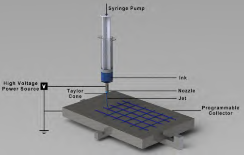
Fig 1. Basic schematic diagram of NFES settings and its components
Near field electrospinning (NFES) has two main parts: spinning and patterning; The former is shared with traditional far field electrospinning (FFES), while the latter is the exclusive advantage of NFES. The device includes high-voltage power supply, nozzle and collector. Since the principle is not too different from that of traditional electrospinning, it is not surprising that the settings of the two are very similar. When an electric field is applied, the force of the electric field overcomes the surface tension of the droplet at the tip of the needle, forming a Taylor cone, and then the ink stretches and thins towards the collector, and all or some of the ink condenses (solidifies) in midair; The fibers are then finally formed on the collector.
According to the characteristics of 3D printing requiring ink-jet, it is combined with high resolution fiber manufacturing technology for micro and nano scale manufacturing and prototyping. In essence, because NFES does not have the chaotic motion of jet, it can produce neatly arranged and patterned fibers. Unlike FFES, NFES can produce 2D and 3D patterns.
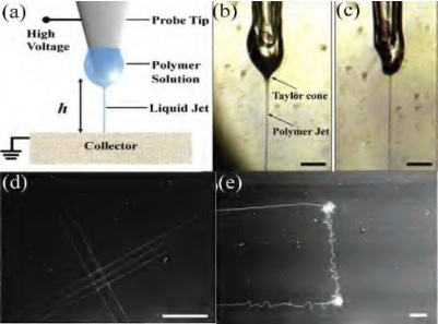
Fig. 2 Schematic diagram of NFES device. (b) Formation of Taylor cone and polymer jet when voltage is applied, (c) shrinkage of probe tip droplets, and (d, e) deposited nanofiber patterns
Table 1 Comparison of advantages and disadvantages between traditional electrospinning (FFES) and NFES
Method | Working distance (cm) | Voltage (kV) | Feed rate (mL/h) | Fiber diameter (μm) | Advantages | Disadvantages and challenges |
Traditional electrospinning (FFES) | 10-15 | 10-50 | 0.1-1500 | 0.01-10 | To produce finer fibers; Simple process; | random mode; Build 3D structure; Solution preparation; |
NFES | ≤1 | 0.2-3 | 0.03-2 | 0.05-200 | Controlled fiber deposition; Ability to make 3D structures; Low voltage | process is complex; Low production speed; |
2. Near field direct write key process parameters
2.1 Solubility
The optimum concentration of polymer solution must be used to start the electrospinning process. At very low concentrations, due to the low viscosity and high surface tension of the solution, polymer particles and islands will appear in the sample. On the contrary, when the concentration increases to a reasonable threshold, the particles change from round droplets to cylindrical, and finally to continuous fibers. The viscosity of polymer solution is closely related to the concentration, and it is expected that there will be corresponding performance. That is to say, when the polymer concentration is very high, the ink becomes very sticky, and the solution cannot be ejected from the nozzle, so the fiber cannot be formed. In contrast, when the viscosity is too low, discontinuous fibers and polymer beads will appear in the sample.
In addition, the conductivity of the solution depends on the characteristics and other components of the polymer and solvent solutions. The increase of solution conductivity leads to finer and more uniform fibers; However, high conductivity will make the jet unstable. Finally, the fiber humidity is inversely proportional to the solvent volatility; When it increases to a certain threshold, the fiber will benefit from a more rounded cross-section (usually observed in dry fibers).
2.2 Process parameters
NFES requires low voltage, mainly due to the short distance from the nozzle to the collector. In addition, although NFES draws lessons from 3D printers and other extrusion based processes, the existence of an electric field between the nozzle and the collector is a serious departure from the basis of extrusion based technologies. As electricity overcomes the surface tension of the polymer and produces jet, the ink is stretched in mid air. With this in mind, it is clear that the voltage intensity will have a significant impact on the fiber.
The feed rate determines the injection rate and the volume of fiber generated. Lower feed speeds are generally more beneficial to NFES because they provide sufficient time for ink to set or cure and prevent liquid from dripping onto the substrate. On the other hand, with the increase of feeding speed, the average fiber diameter and porosity increase, water droplets are generated in the structure, and the fiber humidity increases, especially when the feeding speed is too high.
The inner diameter of the nozzle must be adjusted well, because it is a key feature to prevent needle blockage or ink dripping. Too small diameter may cause needle blockage, while larger nozzle inner diameter will reduce the surface tension of the ink; Therefore, a lower electric field is required to form the jet, thus increasing the jet velocity and fiber diameter.
The distance between the nozzle and the collector determines the jet flight time and stretching, which has a direct impact on the fiber dryness and diameter (i.e., longer working distance and longer flight time will produce thinner and drier fibers). It is important to maintain sufficient distance to allow sufficient solvent evaporation and to suppress the jitter instability of the jet.
Various collectors and fiber collection methods such as planar, rotary, custom 3D printing, liquid and flexible insulation collectors are available in an increasing number of literature. The collector movement significantly affects the fiber diameter and morphology.
2.3 Environmental parameters
Environmental factors such as temperature, relative humidity and environmental gas composition have far-reaching effects on electrospun fibers. The rising temperature will accelerate the evaporation rate and reduce the viscosity of polymer solution. At a relatively low temperature, there are beads in the sample; Therefore, since the fibers should be dried at a reasonable rate, the optimum temperature should be provided. Under the condition of relative humidity, according to the chemical characteristics of the ink, the available water molecules close to the jet will dissolve in it, thus forming porous fibers. In addition, electrospinning in a closed environment can slow down the evaporation of solution because there is too much solution in the atmosphere. In fact, researchers can also improve the repeatability of their experiments by reporting environmental parameters. Finally, summarize the environmental parameters that affect the experiments.
Table 2 Various factors affecting near-field electrospinning (NFES)
Influencing factor | parameters | ||||
Solution | viscosity | concentration | conductivity | surface tension | polymer molecular weight (MW) |
Process | voltage | Feed rate | Nozzle inner diameter | Distance between nozzle and collector | Collector moving speed |
Ambient | Temperature | Relative Humidity | Ambient Gas Composition | ||
3. Near field direct writing application cases and related research
3.1 Electronics
Microcircuits and nano circuits are powerful devices and have become the focus of attention. Despite some advantages, especially in terms of scale and flexibility, manufacturing them remains a challenge. Because most methods are complex, expensive and time-consuming. In addition, they are very fragile structures; Therefore, it is very important to use appropriate materials and designs to ensure the elasticity and integrity of the circuit. A research team designed different electrospun grid like and curved fiber patterns under different conditions (voltage, working distance and deposition rate). It is found that the conductivity is almost independent of the radius of the bending curve, which means that their samples can be appropriately used as flexible electronic devices. In addition, their research is a good indicator of how NFES can reduce costs and become the preferred substitute for micro and nano circuit manufacturing.
3.2 Preparation of patterned fossil graphite carbon fiber
Due to the numerous applications of carbon nanofibers, researchers urgently need more efficient methods of manufacturing process, and NFES has been promising so far. The steps of synthesizing polyacrylonitrile (PAN) based carbon fibers include doping formula, spinning, post spinning process and pyrolysis. A research team has carried out many steps to obtain PAN based carbon nanofibers, and the implementation of NFES is simpler than other carbon nanofiber production technologies. The experiment finally obtained surprisingly thin, strong, and aligned nanofibers, which can be used to make more complex patterns through further research.
Finally, carbon based micro and nano structures can be used to manufacture transparent conductors, photonic crystals, flexible electronic devices, electrochemical sensors and supercapacitors.
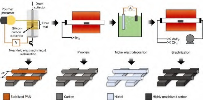
Fig 3 Phase of carbon nanowire manufacturing
3.3 Organization engineering
Tissue engineering combines the principles of biology and engineering, and is helpful to the process of tissue regeneration and healing. Signal factors, stem cells and extracellular matrix (ECM) mimic scaffolds play a key role in tissue engineering. It is well known that scaffold and culture environment can determine the final cell proliferation and differentiation characteristics. Different technologies, such as solvent casting/particle leaching, gas foaming, freeze-drying, solid free form manufacturing, 3D printing and electrospinning, have been used to construct scaffolds. Many of the most common shortcomings of these methods are pore size, random pore size distribution, residual solvents in organic structures, pore isolation and lack of structural reproducibility.
NFES can be used not only to manufacture fiber scaffolds, but also to produce complex designs and geometries. However, its potential is mainly used for cell free scaffolds. After all, most solvents show cytotoxicity, and electric fields may be harmful to cells. On the contrary, some researchers have successfully conducted cell electrospinning low voltage (5-11KV) and biocompatible solvent experiments. Future research can use NFES to embed living cells into 3D fiber patterns. Therefore, it is promising to use low voltage NFES or mechanical drawing technology and develop biological links.
In addition, the scaffold prepared by NFES has certain feasibility in cell orientation, differentiation and tissue growth direction. On the one hand, 3D scaffold assisted cell culture leads to a directional and more stable capillary shaped network, which is due to the use of μ M excellent thickness of tissue supported by well arranged fiber structures. This enhancement is expected, especially for transplantation, because more functional organizations can be obtained.
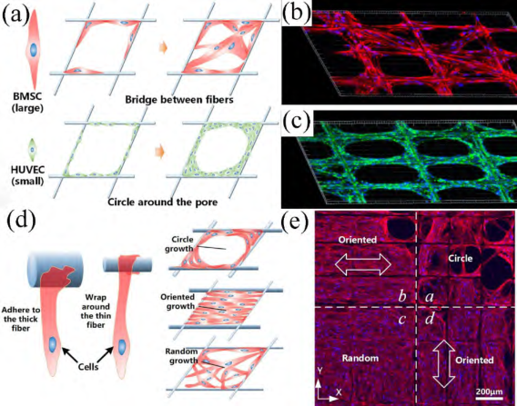
Fig. 4 (a) Schematic diagram of different behaviors of bone marrow stem cells (BMSC) and human umbilical vein endothelial cells (HUVEC) on the same scaffold, in which (b) BMSC showed bridge growth and (c) HUVEC showed round growth. (d) Compare the schematic diagrams of different cell behaviors on thick fibers and thin fibers, and (e) due to the intentional heterogeneity of the scaffold in its four different regions, lead to different cell behaviors.
3.4 Piezoelectric structures and fibers
Wearable and implantable electronic devices are an integral part of human enhancement technology. Although there are moral problems, their attraction and benefits are undeniable. There are many scientific reports on wearable electronic products, focusing on comfort, flexibility, mechanical stability, efficiency and independence of external power supply. Piezoelectric nanofibers are the best way to achieve these properties. These fibers are used for mechanical actuators, energy collection and storage, flexible displays, artificial skin, sensors and biosensors.
In addition, piezoelectric structures can also be used in nano generators using piezoelectric and friction electricity; The self powered pressure sensor that collects vibration frequency from external mechanical force, head movement and simple throat vibration can be used for voice control devices, wearable electronic devices and voice sensing wearable devices with embedded wireless technology.
Reference: doi.org/10.1021/acsabm.1c00944
