Copyright © 2022 Foshan MBRT Nanofiberlabs Technology Co., Ltd All rights reserved.Site Map
1.Fundamentals of Electrospinning
Electrospinning is a simple and universal technology for preparing nanomaterials. In the electrospinning process, the polymer solution is added with thousands to tens of thousands of volts of high-voltage static electricity to generate a strong electric field force between the capillary tube and the grounded receiving device. When the electric field force exceeds a critical value, the repulsive electric field force will overcome the surface tension of the droplets to form a jet, and the charged solution fluid will form continuous fibers under the accelerated tension of the electric field force, forming non-woven nanofibers on the collector. At present, a variety of materials have successfully prepared nanofibers with diameters as low as tens of nanometers by electrospinning, including metal oxides, organic polymers, ceramic materials, and so on.
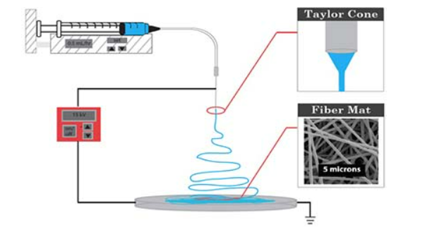
Figure 1 Schematic diagram of electrospinning
2.Electrospinning Control Parameters
2.1 External factors
The external factors affecting electrospinning mainly include the temperature and humidity of the spinning environment, working temperature and heating rate, voltage, solution flow rate, curing distance, and so on. Temperature mainly affects the movement rate of molecules, and the molecular movement rate intensifies, which improves the conductivity of the solution and accelerates the evaporation rate of the solvent, and finally affects the diameter of the fiber. Humidity mainly affects the volatilization rate of solvent, thus indirectly affecting the void distribution on the surface of nanofibers. Calcination temperature and heating rate mainly affect the final fiber formation of the spinning precursor.
The voltage mainly affects the fiber diameter in the spinning process. The electric field force is less than the viscous force of the solution, so fibers cannot be formed; When the voltage increases to a suitable value, the electric field force is slightly higher than the viscosity of the solution, and it is easy to stretch into fibers; As the voltage continues to increase, the fiber stretching speeds up, and the repulsive force between charged particles gradually increases, and the spun fiber will appear bifurcation phenomenon, which makes the diameter of the fiber smaller. When the voltage exceeds the critical value, the field strength is too large, which will cause part of the solution to be directly transferred to the receiving plate without enough stretching time.
The speed of solution flow rate mainly affects the stretching of fiber and solvent volatilization. Under the optimal flow rate, the solvent volatilization time is long enough, and the fiber can be fully stretched so that the morphology of the obtained fiber is better and the diameter is smaller. The curing distance mainly affects the spinning morphology by affecting the electric field strength and solvent evaporation rate.
2.2 Internal factors
Internal factors are mainly caused by various parameters of the solution, such as viscosity, conductivity, and surface tension of the solution. The solution viscosity mainly affects the forming condition of the material fiber. When the viscosity of the solution is too low, it is easy to cause the solution to be unable to be stretched under the action of electric field force, and directly move to the collection plate in the form of droplets; When the viscosity of the solution is too large, the electric field force cannot stretch the solution effectively, so normal spinning cannot be carried out. The conductivity of a solution mainly depends on the conductivity of various components in the solution. Within a more appropriate conductivity range, the conductivity of the solution is strong, and the ability of a solution to be pulled under the action of electric field force is strong, which is easy to form fibers. The surface tension mainly affects the fiber morphology. The surface tension is too high, and the effect of electric field force cannot overcome the liquid surface tension, resulting in the instability of the jet in the spinning process, and fibers in the form of droplets or beads will appear; Under low surface tension, the fibers with the relatively uniform surface can be obtained.
2.3 Electrospinning Materials
Commonly used materials include PVDF, pan, PA, PES, PU, PLA, PS, etc. in biomedicine, commonly used materials include PEO, PCL, PLGA, PLA, collagen, silk fibroin, hyaluronic acid, chitosan, chitin, etc; In terms of battery diaphragm, commonly used materials include PI, Pei, PVDF, PMIA, etc; In terms of waterproof and moisture permeability, commonly used materials include Pu, PVDF, etc; In terms of adsorption and separation, commonly used materials include Ca, pan, chitosan, etc.
3.General electrospinning setup
The basic electrospinning device consists of four main components: a high-voltage power supply that provides high-voltage electrostatic field force, a syringe with a jet needle, a syringe pump, and a grounded receiving device. DC power supply is generally used to supply high-voltage power, rather than AC power supply. The high voltage required for electrospinning is 1 ~ 30KV. A syringe (or pipette) conveys solution or melt to the spinneret at its end, which is a very thin metal tube. The collecting device or receiving plate is used to collect nanofibers. The common one is the drum collecting device. By changing the geometric size and shape of the collecting device, the arrangement of nanofibers can be adjusted.
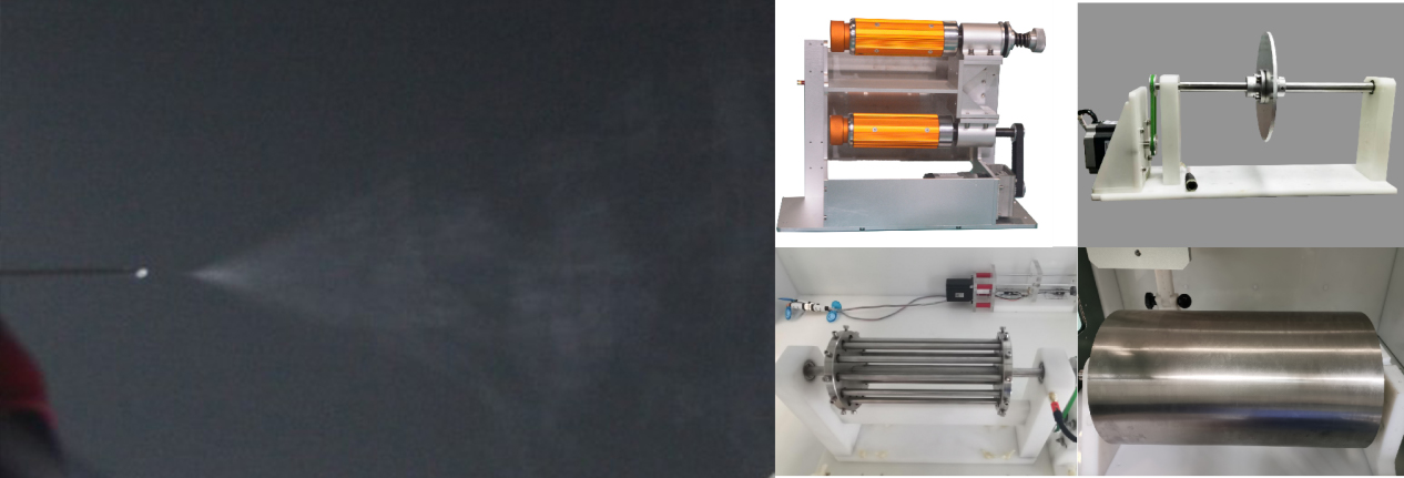
Figure 2 Electrospinning device and various collectors
The nozzle device can be replaced according to the experimental needs, and the common one is the single needle device. The electrospinning of two materials requires an additional nozzle module and syringe. When it is necessary to increase the output of nanofibers, it is necessary to configure a multi-needle nozzle device. At present, the multi-needle nozzle module is widely used in electrospinning production lines. Another way to increase the output of nanofibers is to add an airflow nozzle at the nozzle and connect a gas source externally. For air-assisted electrospinning, this method is called solution blown spinning (SBS). The assistance of airflow can help to increase the output of electrospinning, reduce the spinning time, and greatly increase the selection range of materials. In short, the development process of the nozzle is also the process of improving spinning efficiency. The continuous development of nozzle makes electrostatic spinning equipment more suitable for industrial production.
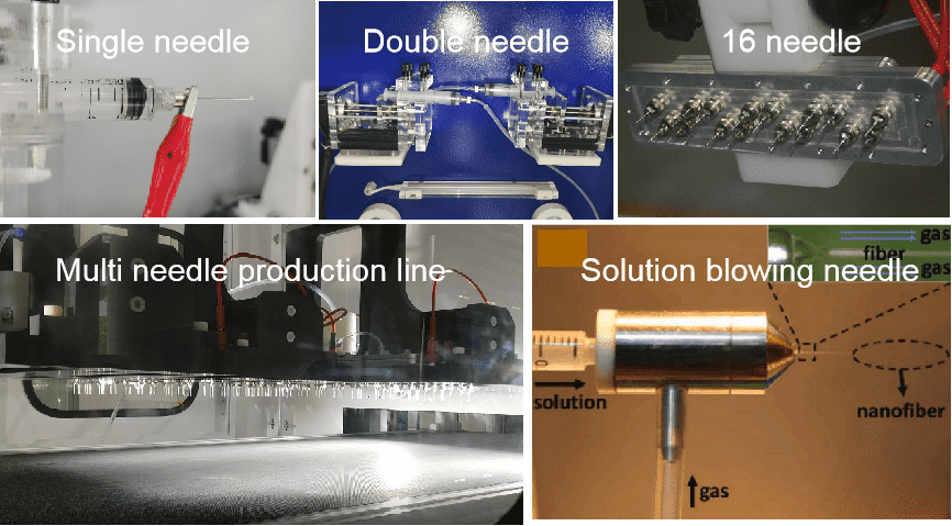
Figure 3 Various electrospinning nozzles
In addition to the basic movable module, the electrospinning system should have the function of controlling the spinning environment to facilitate the adjustment of the ambient temperature and humidity during the experiment. Some equipment will have external dehumidifiers and heaters, and some equipment will integrate dehumidification and heating function modules into the equipment and control them through the operation interface. Because the temperature and humidity during the experiment will cause many uncertain effects, the electrostatic spinning equipment on the market will generally integrate the environmental control module.
4.Electrospun nanofiber structures
A single fiber called 1D structure will have different forms. Among them, uniform nanofibers with smooth surfaces and uniform cross-sections are the most basic electrospun fibers, which are easy to form. The core-shell (Fig. (e)), hollow (Fig. (f)) and multi-channel (Fig. (a) - (d)) nanofiber structures are called coaxial nanofibers. Coaxial electrospinning (co electrospinning) is derivative nanotechnology, which improves traditional electrospinning. Coaxial fiber has compa lex internal structure, unique anisotropy, and large specific surface area; Therefore, they have high transmission efficiency. Because coaxial nanofibers can be used to realize the controlled release of drugs, they are widely welcomed in the fields of biotechnology and drug delivery.
In some cases, nanofibers under the microscope have Beaded morphology. The change in electrospinning parameters will lead to many changes in the physical and chemical properties of electrospun materials. The combination of electrospinning and electrospray using low viscosity coaxial spray fluid and high viscosity spray lining fluid for the outer layer is used to produce Beaded heterostructure fibers.
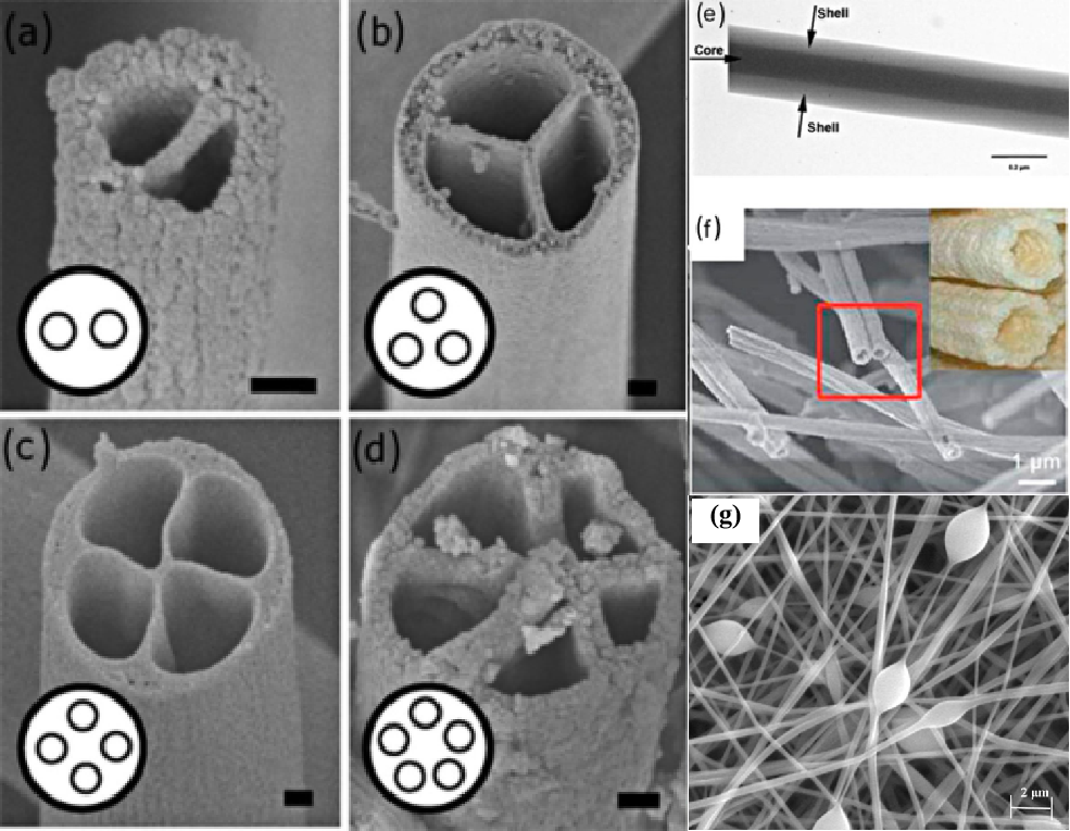
Figure 4 (a) – (d) multi channel fiber; (e) Solid coaxial fiber; (f) Hollow fiber; (g) Beaded structure
Configuration of Electrospun Nanofibers: (1) random orientation structure: due to the bending instability of the high charge jet, the nanofibers are deposited on the surface of the conductive plate or rotating conductive drum show random orientation chaos. Randomly oriented nanofibers are deposited in the form of nonwoven mats, with high porosity of about 50% to more than 90%. (2) Oriented Nanofibers: continuous linear arrangement of yarns can be manufactured by replacing traditional electrospun collectors with custom collectors, high-speed rotating collectors, or arrangement needles. Some tissues, such as cartilage [77], tendons [78, 79], ligaments [78], blood vessels [73], nerve conduits [80, 81], etc. It is composed of arranged fibers and oriented cells, which can guide the proliferation of such cells.
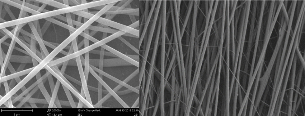
Figure 5 Disordered nanofibers and oriented nanofibers
Three-dimensional structure of nanofiber scaffolds: a lot of research is devoted to improving the bionic performance of electrospun fibers, and using auxiliary equipment or improved electrospun devices to manufacture 3D scaffolds.
3D printing technology is a technology to assist in the preparation of 3D nanofiber scaffolds. 3D printing combined with electrospinning can completely encapsulate cells in the middle layer to realize cell function. The second is near-field direct writing (NFDW) electrospinning. Due to the instability of the jet, electrospinning using conventional solutions produces highly disordered fibers. To enhance the adjustment of the deposition position of electrospun fibers, the distance between the needle and the collector can be reduced to suppress the jet instability. Sun et al. Proposed a new electrospinning method, called near-field electrospinning (NFES), and then developed it into technology and mew. By reducing the applied voltage and the gap between the spinneret and the receiver, a single fiber with a diameter from tens of nanometers to hundreds of microns can be deposited in a direct, continuous, and controllable manner to form a characteristic pattern. It is worth noting that this method can be used to manufacture well-supported supports with large apertures and specific patterns. Therefore, it is widely used in multi-layer tissue engineering scaffold assembly and microelectronics.
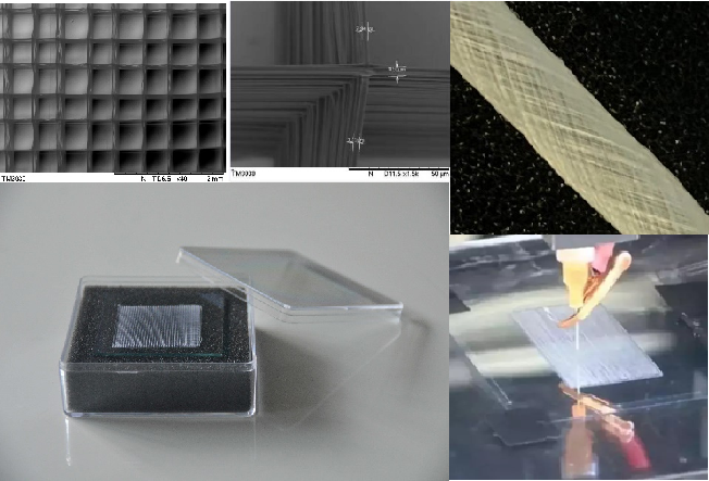
Figure 6 Near-field direct writing ordered nanofiber sample
Advantages of three-dimensional nanofiber scaffolds: (1) biocompatibility and toxicity; (2) Mechanical properties and degradation behavior in vivo; (3) Appropriate pore size and porosity; And (4) the ability to regulate cell behavior. In addition to the planar structure, electrospun stents can also be developed into curved vascular stents. Compared with 2D wound dressings, 3D scaffolds have better mechanical properties and can support cell adhesion, proliferation and migration.
Reference
[1] Zhong, H., Huang, J., Wu, J. et al. Electrospinning nanofibers to 1D, 2D, and 3D scaffolds and their biomedical applications. Nano Res. 15, 787–804 (2022). https://doi.org/10.1007/s12274-021-3593-7
[2] Glebert C. Dadol, Ali Kilic, Leonard D. Tijing, Kramer Joseph A. Lim, Luis K. Cabatingan, Noel Peter B. Tan, Elena Stojanovska, Yusuf Polat, Solution blow spinning (SBS) and SBS-spun nanofibers: Materials, methods, and applications, Materials Today Communications, Volume 25, 2020, 101656, ISSN 2352-4928. https://doi.org/10.1016/j.mtcomm.2020.101656.