Copyright © 2022 Foshan MBRT Nanofiberlabs Technology Co., Ltd All rights reserved.Site Map
1. Abstract:
The huge gap between inadequate clean water supply and demanding human needs can be narrowed by sustainable and green methods of solar-driven evaporation, which efectively converts solar energy into thermal energy to purify seawater and wastewater. This article reviews the recent progress of electrospun nanofber-based evaporation systems, This review updates the progress of electrospun nanofber evaporation systems and simultaneously stimulates attractive research on designing electrospun nanofber-based photothermal systems for applications in solar water evaporation, photothermal therapy, electricity generation, and other related areas.
Based on the advantages of electrospinning nanofibers with high specific surface area, high porosity, adjustable structure, super flexibility, and various doping technologies for solar energy materials,the nanofber-based materials prepared by electrospinning technique show a great potential for clean water generation through solar evaporation from saline water and polluted wastewater (Fig.1). As shown in Fig. 1. Electrospinning classifcations, polymers, and available solar materials in electrospun nanofber evaporators are presented in detail.
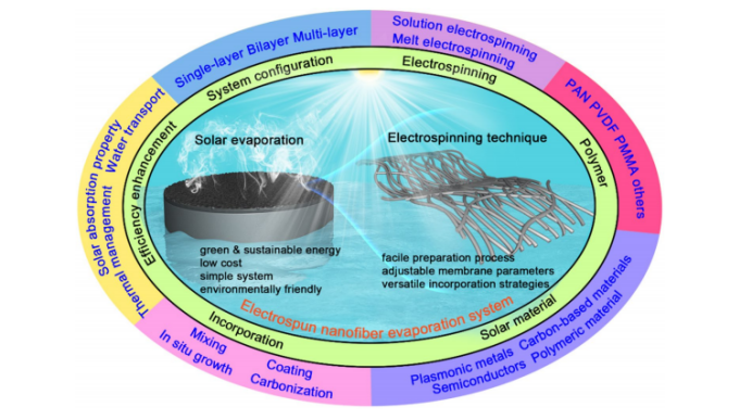
Fig. 1 Schematic diagram of the overall electrospun nanofber evaporation system covered in this review
2.Research Highlights:Incorporation Strategies of Solar Materials in Electrospun Nanofber Evaporation Systems
Solar-absorbing materials can be incorporated in electrospun nanofber evaporation systems by various methods. However, systematic organization and reasonable categorization are essential and urgent for a better understanding and development of electrospun nanofber evaporation systems. The incorporation strategies of solar-absorbing materials in electrospun nanofber evaporation systems can be categorized into four diferent techniques, namely mixing, coating, carbonization, and in situ growth.
2.1 Mixing:
Mixing is commonly used in electrospun nanofber evaporation systems, and can be classifed into pre-mixing and post-mixing. Pre-mixing of solar materials in a polymeric solution before electrospinning is the most convenient and widely used method (Fig. 2a). Upon dispersion into polymer solutions, solar absorber materials can be easily encapsulated in the resultant electrospun nanofber materials. For example, Chen et al. fabricated electrospun PCL/CNTs/CNPs composites for solar steam generation.During the preparation, functional solar materials of CNTs or CNPs were mixed in PCL solution to yield a homogeneous spinning solution. In a similar approach, a GO/PVA electrospun nanofber evaporator was constructed for solar water evaporation, in which GO powder and PVA were mixed in water to form the electrospinning solution . Alternatively, post-mixing can incorporate solar materials into 3D-structured materials (e.g., aerogels, hydrogels, and alcogels) using electrospun nanofbers as the skeleton (Fig. 2b).
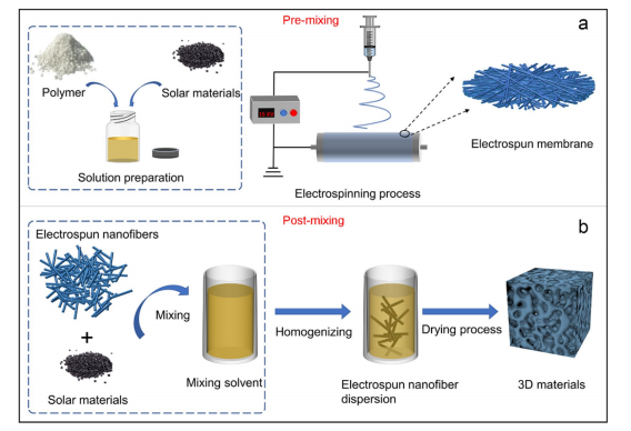
Fig. 2 Schematic diagrams of mixing for solar material incorporation in electrospun nanofber evaporation systems: (a) pre-mixing and (b) postmixing
2.2 Coating:
Coating has been intensively developed for the incorporation of solar absorber materials into electrospun nanofber evaporation systems. Coating can be performed in various ways, such as dip-coating, spray-coating, spin-coating, rollcoating, blade-coating, vapor deposition, and electrophoretic deposition.Among them, dip-coating and spray-coating are most widely applied in electrospun nanofber evaporators. Dip-coating can be used conveniently to endow the photothermal property to the electrospun materials by immersing them in a suspension solution flled with solar materials (Fig. 3a).
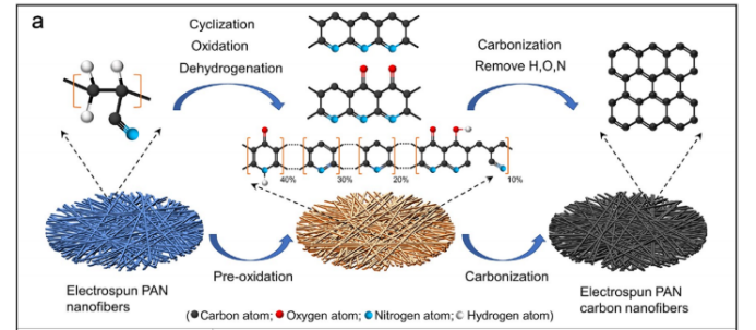
Fig. 3 Schematic diagrams of coating for solar material incorporation in electrospun nanofber evaporation systems: a schematic diagram of dip-coating and spray-coating.
2.3 Carbonization:
Carbonization can convert electrospun PAN nanofbers to diferent forms of carbon fbers to be used in electrospun nanofber evaporators. The preparation of PAN carbon fbers proceeds to three main stages: electrospinning fabrication, pre-oxidation, and carbonization (Fig. 4a). In electrospinning, PAN polymer is dissolved in a solvent, such as dimethylformamide, dimethylacetamide, or dimethyl sulfoxide. The as-spun PAN nanofbers are rapidly formed under electrostatic drawing and solvent volatilization. Preoxidation is generally carried out in the air between 180 and 300 °C, which is a key stage where thermoplastic and linear PAN macromolecular chains are transformed into a non-plastic ladder structure with heat resistance. This enables them to maintain their fber morphology and thermodynamic stability during high-temperature carbonization. In the pre-oxidation stage, as-spun PAN fber is subjected to very complex physical and chemical changes, including cyclization, oxidation, and dehydrogenation reactions(Fig. 4a).
The resultant PAN carbon nanofbers can be used in electrospun nanofber evaporation systems in three forms:
(1) directly used as a photothermal layer in electrospun nanofber evaporators (Fig. 4b),
(2) adding the ground carbonized PAN powder to other matrices or 3D materials to form photothermal composites (Fig. 4c),
(3) constructing 3D materials based on the electrospun PAN nanofber frst, followed by carbonization to build photothermal composites (Fig. 4d).
Carbonization can form PAN-based carbon membrane directly for solar water evaporation. Other advantages include high solar absorption ability and adjustable membrane structure. Moreover, PAN is currently the primary and almost the only raw material available for carbon fber through carbonization. However, the poor mechanical properties of carbon fber and high energy consumption during carbonization are the main concerns for commercial production and implementation.
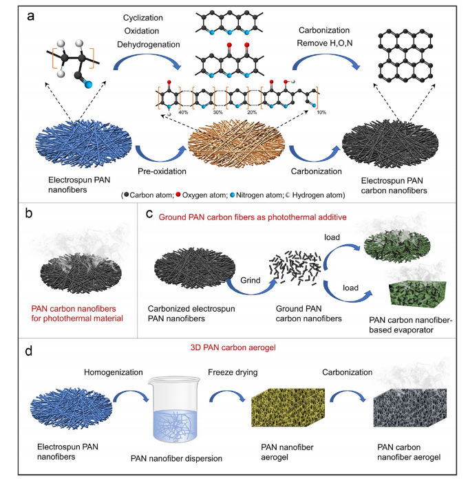
Fig.4 Schematic diagrams of coating for solar material incorporation in electrospun nanofber evaporation systems: a schematic diagram of carbonization, b PAN carbon nanofbers directly used in electrospun nanofber evaporation systems, c ground carbonized PAN fbers as a photothermal additive for the 3D evaporator, and d constructing 3D materials based on the electrospun PAN nanofber.
2.4 situ growth:
In situ growth is one of the most versatile methods for material loading but is rarely applied in electrospun nanofberbased photothermal systems. However, such an approach shows excellent prospects for embedding functional solarabsorbing materials on electrospun nanofber evaporators. In fact, various solar-absorbing materials like plasmonic metals, semiconductors, carbon, and plasmonic materials can be planted on the electrospun nanofbers by in situ growth. Various methods are available for in situ growth. Among them, the liquid and the vapor phases in situ growth are exceptionally convenient and promising for the incorporation of solar materials in electrospun nanofber evaporators. During the growth process, photothermal materials are loaded on the surface of a substrate (e.g., nanofbers) in a gas- or liquid-phase atmosphere through chemical reactions.Sun et al. synthesized a desalination membrane through in situ growth of CNTs on the electrospun silica nanofbers using chemical vapor deposition (Fig. 5a). The resulting composite membrane showed ultra-rough and porous interface structure that resulted in stable water fux and high salt rejection of>99.9%.
According to the work of Kim et al. , CNTs were successfully in situ synthesized on the electrospun carbon nanofbers by optimized temperature-controlled process. Lu et al.reported 3D core-shell hierarchical electrospun carbon nanofber-based heterostructures, where the TiO2 and molybdenum disulfde (MoS2) nanosheets were grown in situ onto the carbon nanofbers separately (Fig. 5b). Molco et al.fabricated metalorganic framework (MOF)-embedded electrospun fbers via two steps. Initially, polymer solutions containing the MOF precursors were fabricated into nanofbers; subsequently, the MOF in situ growth was initiated by antisolvent-induced crystallization. Figure 8c shows the electrospun nanofbers, in situ growth of MOF, and an enlarged image of the MOF. Li et al.reported that the transition metal sulfdecomposites NiMoS3 nanoparticles were in situ grown onto the electrospun carbon nanofbers via vulcanization.
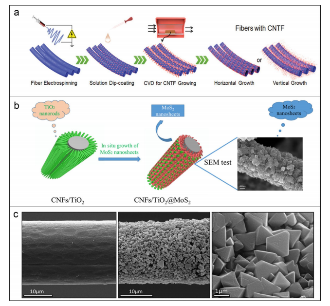
Fig.5 Schematic diagrams of coating for solar material incorporation in electrospun nanofber evaporation systems: a schematic diagram of CNT forest growth on electrospun silica nanofbers.b schematic diagram of TiO2@MoS2 in situ growth on electrospun nanofberf. c SEM images of electrospun nanofbers, MOF embedded fbers, and enlarged image of MOF.
3.Conclusion:
Electrospinning materials play an important role as a medium in absorbing solar energy, transferring heat, and evaporating water in the evaporation system. This article reviews the research progress of electrospun nanofibers for purifying water, including evaporation systems. The integration strategy of solar energy and the material and system structure of electrospun nanofibers were systematically discussed in the evaporator. Four strategies, namely mixing, coating, carbonization, and in-situ growth, have been used to combine solar materials into electrospun nanofiber evaporation systems. The solar evaporation performance of electrospinning can be enhanced by adjusting the solar absorption characteristics, thermal management of the nanofiber evaporation system, or by using clever waterways. For evaporators based on electrospun nanofibers, precise structural design is effective in enhancing solar energy absorption, thermal management, and water supply. In the practical application of electrospinning nanofiber evaporation systems, establishing standard evaluation methods for efficiency is crucial for comparing and improving the performance of different electrospinning nanofiber evaporation systems.
Paper link:https://link.springer.com/article/10.1007/s42765-023-00286-4